Machine Translated by Google
Fabrication of polymer thin films by using the Micro-dip-coater
Preparation of polymer thin films using a micro dip coater Tomoo Nagayama, Graduate School of Engineering, Osaka University
There are many fabrication methods of polymer thin film. In this report, dip-coating method, which is the one of such methods using polymer solution, was examined using commercially available resin. As the result, thicknesses of polymer films were dependent on the concentration of polymer solution and on the withdrawing speed. Although that dependence for the speed did not agreed with the theoretical formula, the widely control of the thickness is possible by the withdrawing speed and the solution concentration.
1. Introduction
Generally, polymer membranes are formed by the polymerization of polymer solutions.A wet process is used.
Pin coating method, wire bar coating method, cast method There are various types, depending on the desired film thickness.
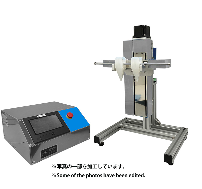
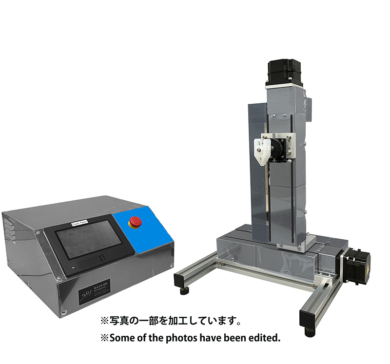
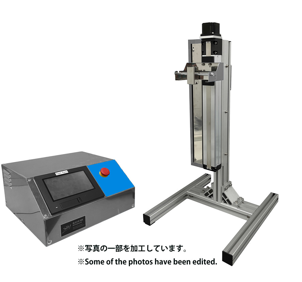
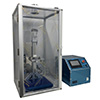
Each of them is used differently. This time, a micro dip coater (SDI Corporation, Fundamentals of polymer thin film fabrication using MD-0408 The experimental results are reported.
2. Film formation using general-purpose resins
In the future, it will be used as an insulating film for the semiconductor layer of FET elements.We are considering the production of thin semiconductor films.
First, we used a general-purpose polymer to measure the concentration of the sample solution and the matrix.
The lifting speed of the Microdip Coater determines the production speed.
The difference in the thickness of the film was examined.
2-1 Film forming conditions
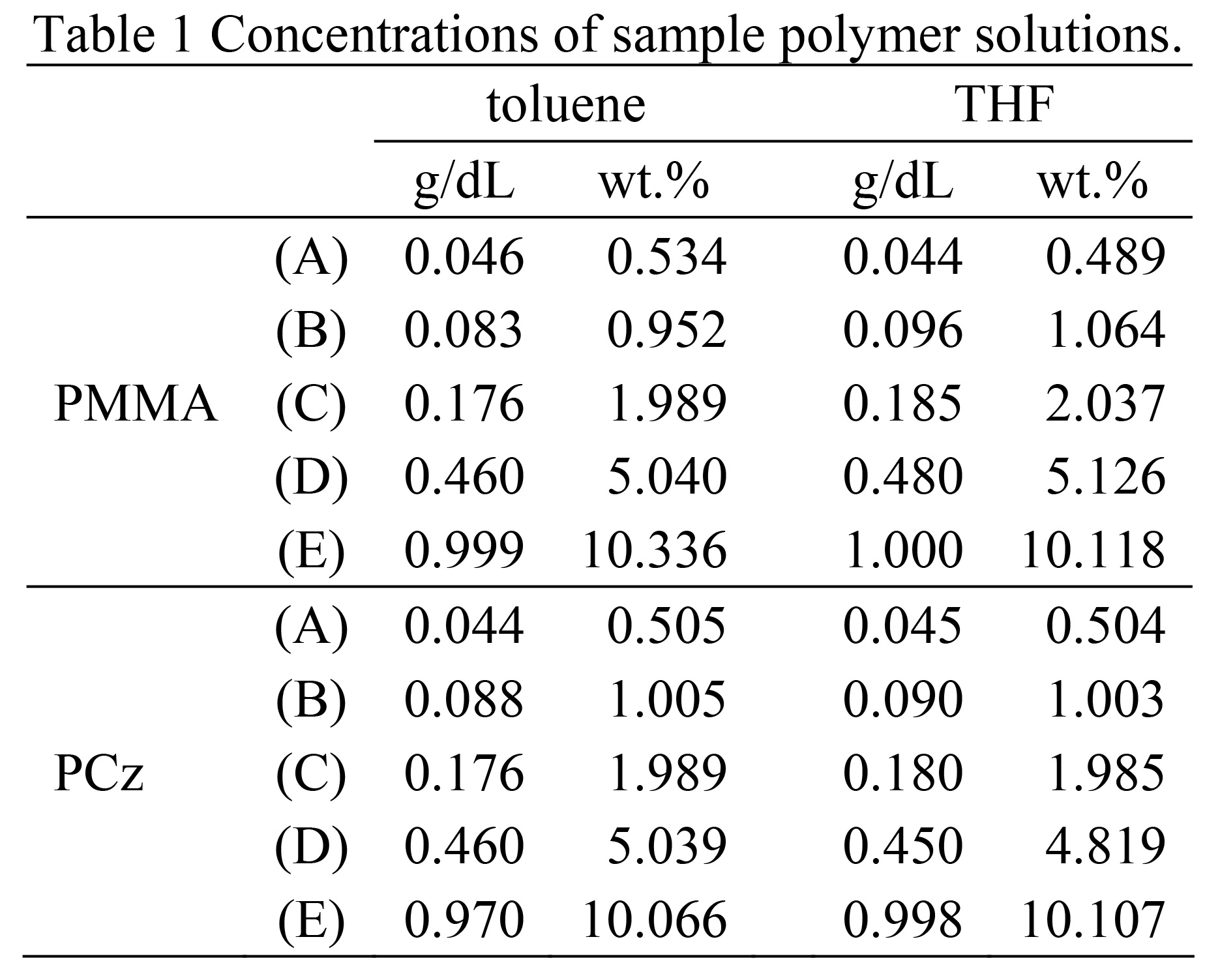
The general-purpose polymers include poly(4,4'-cyclohexylidene- diphenylcarbonate) (PCz: provided by Kyocera Mita, Molecular weight unknown) and poly(methyl methacrylate) (PMMA: manufactured by Aldrich, Mw=101,000) were used.The sample solution consisted of each polymer in toluene and Approximately 3mL at concentrations of 0.5, 1.0, 2.0, 5.0, and 10.0wt.% in THF The concentration of the prepared sample was adjusted to be 100% by weight.
The concentrations, expressed in units of g/dL, are shown in Table 1.
The substrate was a glass slide cut to 8 mm x 35 mm.
The following was used.
The micro dip coater used in this study (Mitsubishi Microelectronics, Inc.) SDI, MD-0408) has a travel speed of 0.001 to 40.000 mm/sec Variable in 8 steps, programmable for moving and stopping
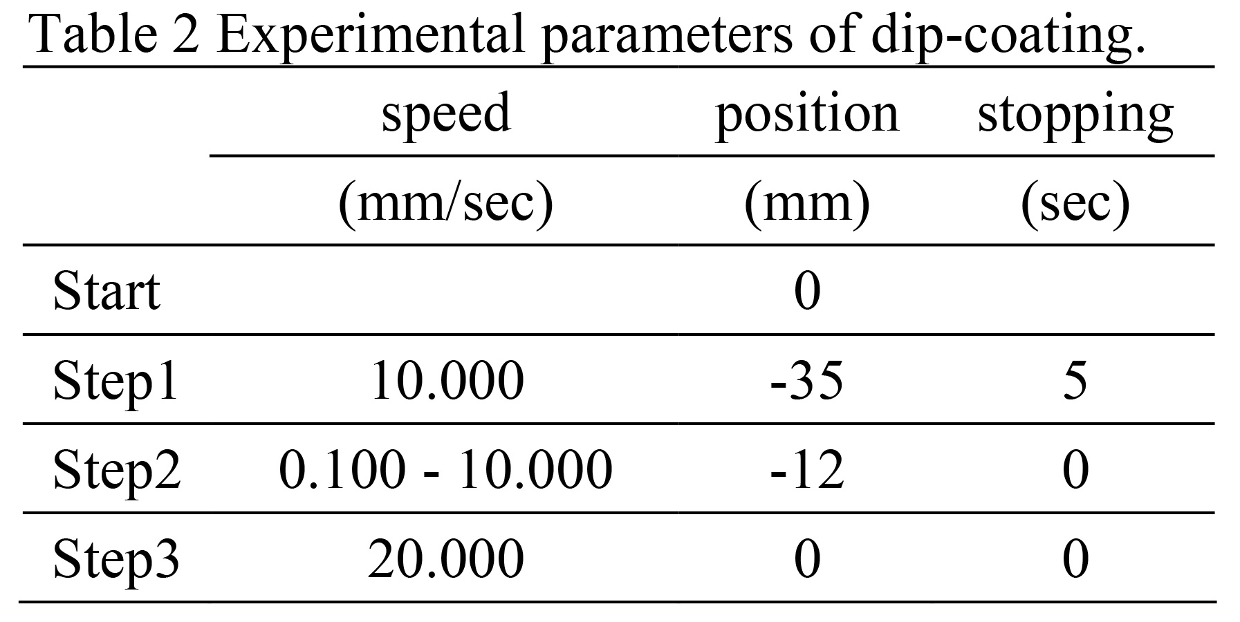 n this case, the following is shown in Table 2.
In the steps shown, the board is placed 10.0 to 15.0 mm below the The film was formed in the following condition (the length of this part is The difference occurs depending on the liquid level.) The lifting speed is 0.100, 0.200, 0.500, 1.000, 2.000, 5.000, 10.000 There are seven types: The film-forming environment was a dehumidified laboratory at 25°C.
The air conditioner was set to the state it was in after operating for three hours.
2-2 Film thickness evaluation method
To evaluate the thickness of the film after deposition, a stylus-type step gauge was used.(DekTak 3st) was used at four different locations on each sample.
The deposition was started from the top of the substrate (i.e., the deposition start point) at a distance of 2.0 mm.
A line 10.0 mm long from the point to the film-forming area 8.0 mm away The profile was used to determine the film thickness.
A typical line profile is shown in Fig.1.
The sample was prepared by using PCz as the polymer and the solution concentration was high.
The pulling speed was fast, so Rapid drying causes the polymer film surface to The surface has an uneven structure that is unique to resin.
In the case of the material, the relatively flat area (area (c) in the figure) The average value was taken as the film thickness of this sample.
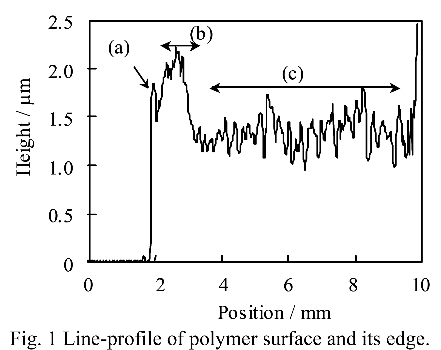 Looking at the initial shape of the film, at the starting point (a), Now, due to the edge effect, it is more raised than other parts. Curiously, after that, about 2.0 mm
After a gentle rise occurs, the flat area
This shape has a surface shape on the order of nm.
Looking at the initial shape of the film, at the starting point (a), Now, due to the edge effect, it is more raised than other parts. Curiously, after that, about 2.0 mm
After a gentle rise occurs, the flat area
This shape has a surface shape on the order of nm.The results were also observed when the sample was placed on a flat thin film.
This is not due to the concentration or lifting speed.
This is thought to be because the particles initially adhered to the substrate. The solution is pulled downward by gravity, but film formation is promoted.
If the solution is also present at the top, the tension and weight The forces remain balanced, resulting in a uniform liquid film.
These results are considered to be Polymer film formation using a dip coater is Auniformfilmcanbeobtainedfromabout2mmabovetheliquidsurface.
This means that:
2-3 Relationship between film thickness and pulling speed
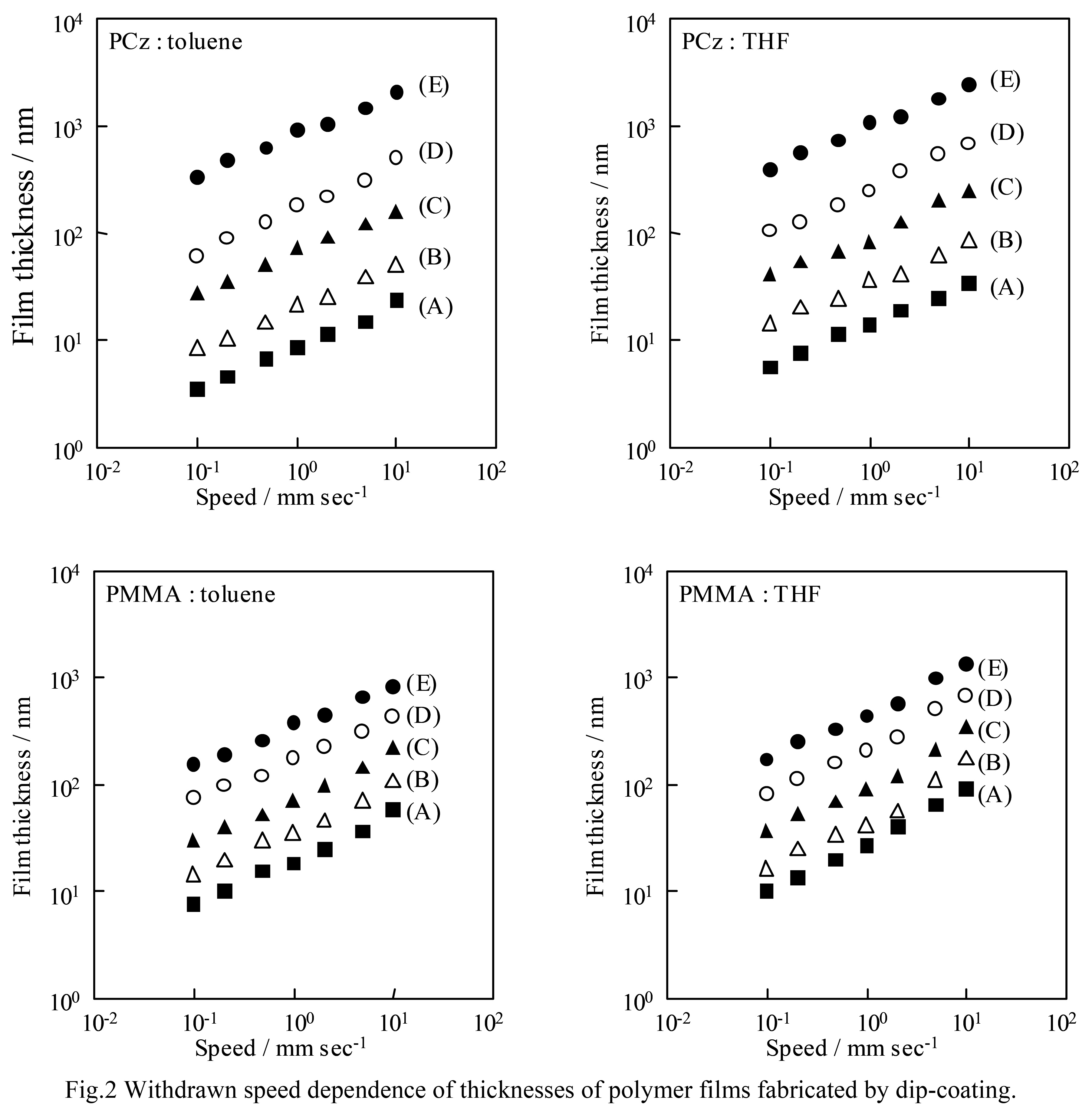
Log-log plot of film thickness and pulling speed for each sample The results are shown in Fig. 2. In all conditions, the log-log plot A linear relationship was obtained for the lot. The slope of the relationship was Using the least squares method, the value was calculated to be 0.4 to 0.5.Polymer thin films prepared using a dip coater The thickness of the film is the same regardless of the sample solution. This means that the temperature rise rate depends on the When forming a film from the same solution, the sample is If the film thickness is known, it can be made at other speeds. The thickness of the sample can be easily estimated.
This means: Here, the thickness of the thin film formed by the dipping method is 1 It is known that the following equation can be used to express .
This means that the micro Polymer thin films prepared using a dip coater The thickness of the film is the same regardless of the sample solution. This means that the temperature rise rate depends on the When forming a film from the same solution, the sample is If the film thickness is known, it can be made at other speeds. The thickness of the sample can be easily estimated.
This means: Here, the thickness of the thin film formed by the dipping method is 1 It is known that the following equation can be used to express .
 Considering this formula, other conditions than the pulling speed
All things being equal, film thickness is proportional to the 2/3 power of velocity.
Considering this formula, other conditions than the pulling speed
All things being equal, film thickness is proportional to the 2/3 power of velocity.In other words, the slope of the log-log plot is However, the experimental value The plot of 0.4 to 0.5 gives slightly smaller values. It is being done.
2-4 Relationship between film thickness and sample solution concentration
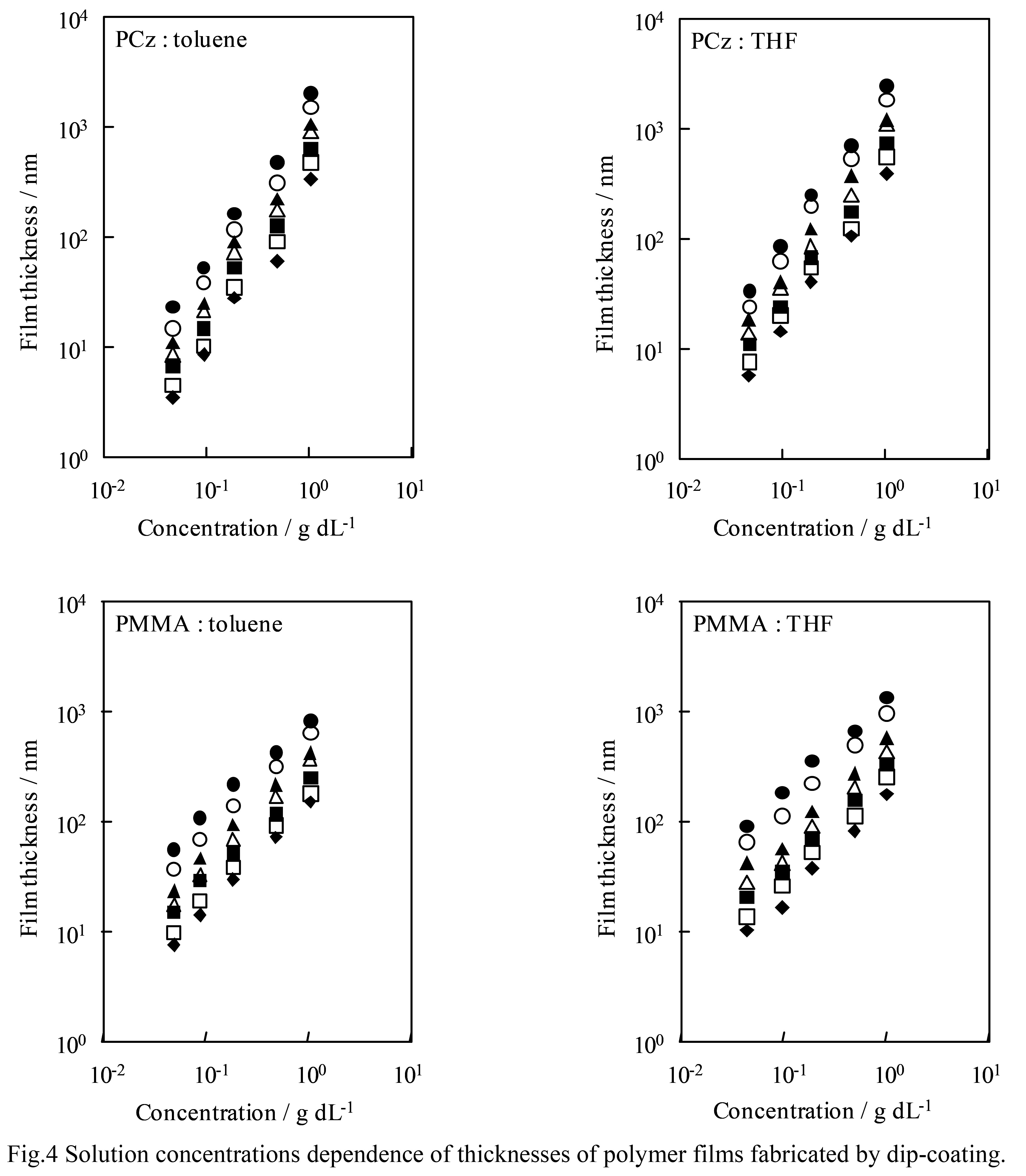
Next, a log-log plot of the solution concentration for each film thickness is is shown in Fig. 4. As before, almost all conditions The log-log plot shows a linear relationship.This means that the film thickness also depends exponentially on the concentration. In equation (1), the concentration term is The factors that affect the viscosity of the solution are the viscosity, density, and surface tension. However, the relationship between each factor and solution concentration The relationship between the degrees is very complicated, and the slope of the line and It is difficult to estimate the exponential part that becomes the polynomial.
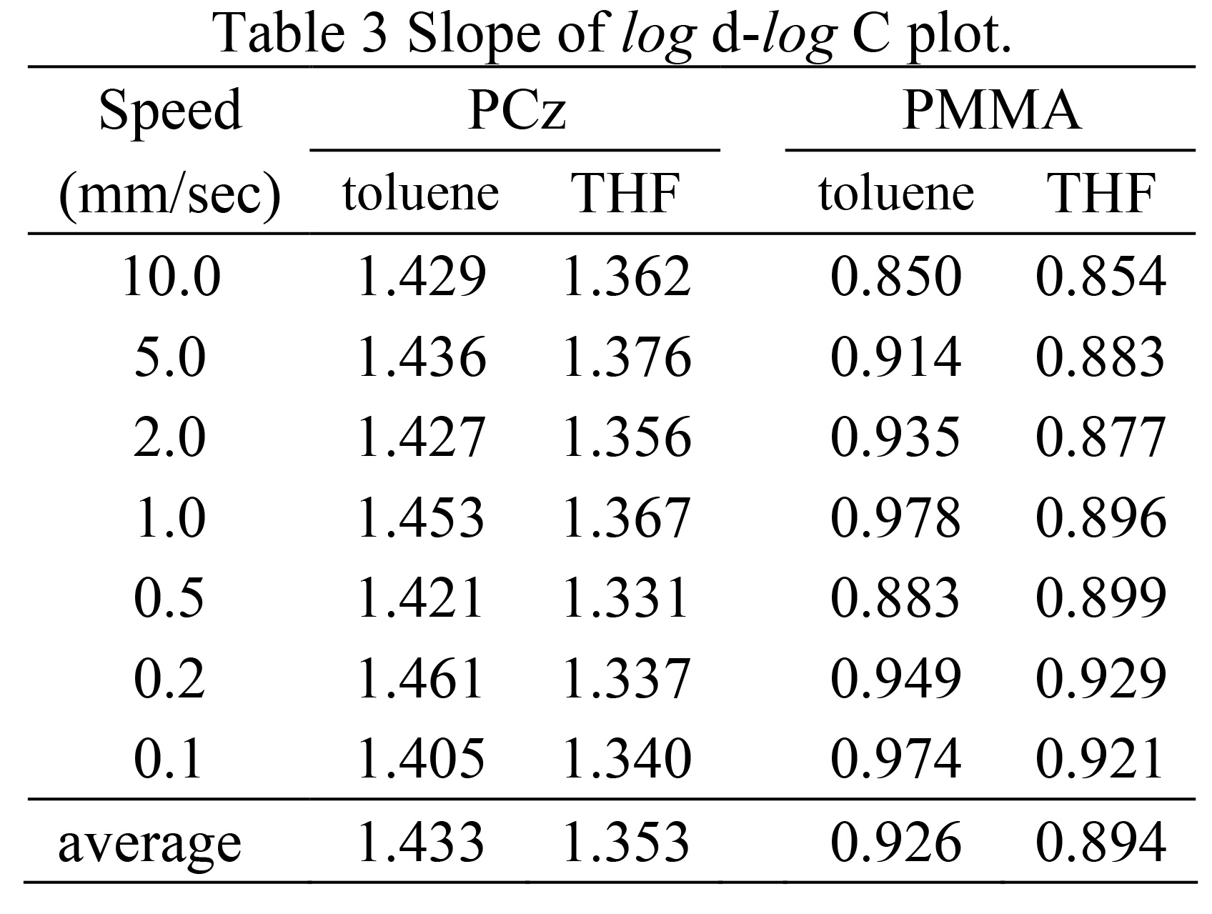
The values are consistent regardless of the type of mer or solvent. However, in Fig. 4, the slope varies depending on the polymer. You can see the difference between the upper and lower graphs. In fact, the slope was calculated using the least squares method.
However, the values for PCz were about 1.4 and for PMMA about 0.9.
The results were as shown in Table 3. The solvent did not affect the results.
However, the value was large for toluene and small for THF.
This is because the solution viscosity, density, and surface tension depend on the polymer species.
This means that the types of The solution viscosity depends on the structure of the polymer. The difference in the slope obtained this time is due to the difference in solution viscosity. It was speculated that this was the case.
2-5 High concentration solution - Problems when pulling up slowly
As described above, a micro dip coater was used.This allows for a very wide range of film thickness control.
However, in order to obtain a thick film, The solution concentration must be increased, and dripping occurs.
It is believed that this phenomenon will have a large impact.
In the experiment conducted this time, the sample solution had a concentration of 5 wt.% or more.
When used, the cloudiness during drying and the formation of a resin structure are Also, over time, some liquid may drip out.
The former was observed to be cloudy due to spin coating or Other methods such as wire bar coating also have problems.
In this respect, the surface roughness caused by the evaporation of the solvent These can be removed by selecting the right solvent when preparing the solution.
The latter is explained in Section 2-1.
As mentioned above, the starting point of film formation (where the thick part occurs) This is not a problem if you use the central part.
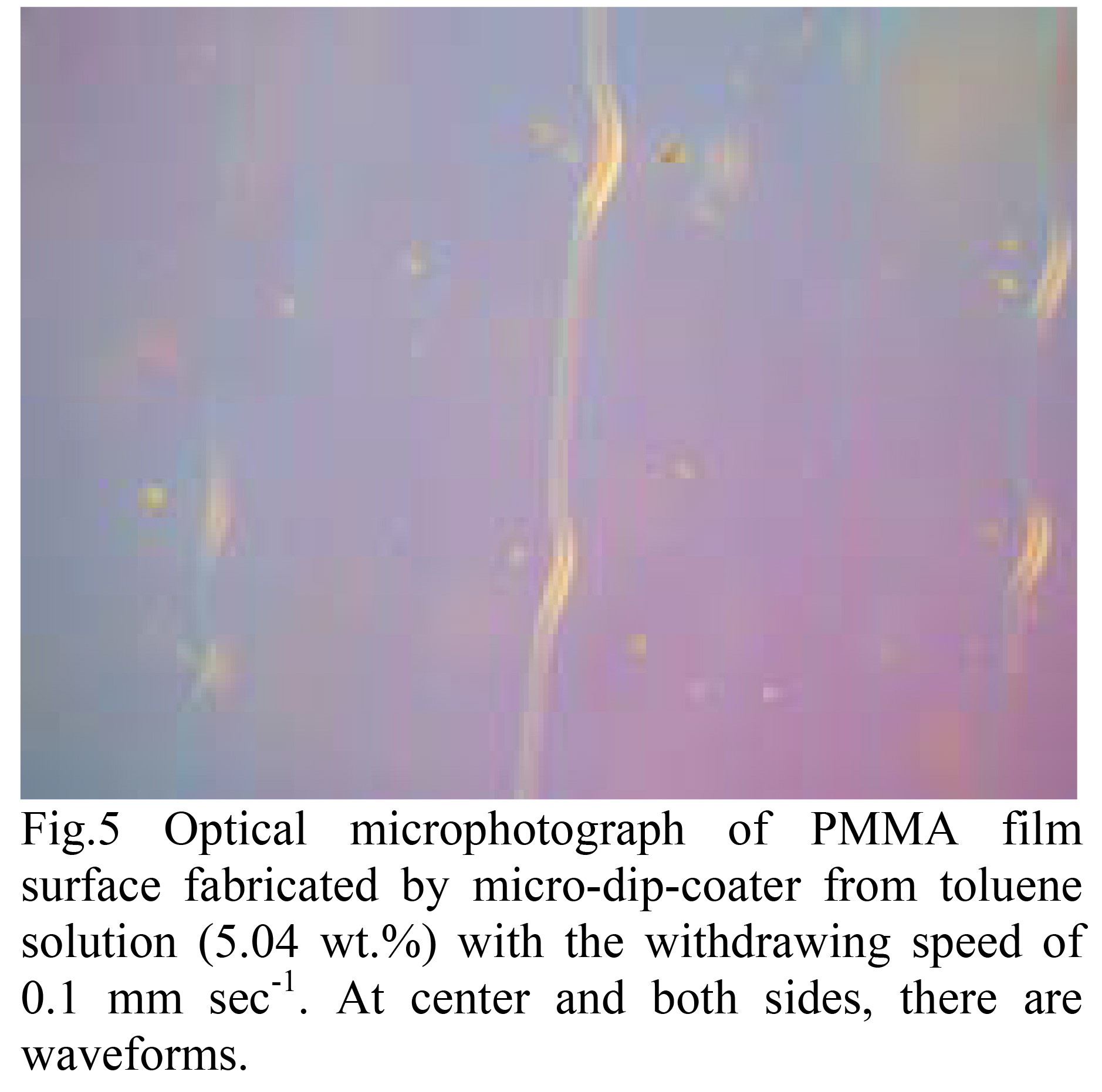
In addition to this dripping, another problem is the use of highly concentrated solutions.
When the slow pulling is performed using It was found that surface roughness was formed.
For example, there are three lines on the right, center, and left of the photo.
It can be seen that a swelling like this has formed.
If the viscosity of the solution is too high, the solution may not adhere to the substrate.
When the tension balance is lost, the liquid This causes a periodic fluctuation in the liquid level, where the liquid level drops.
This is the same as when dipping.
We plan to clarify this further by observing the liquid surface.
3. Conclusion
In this report, PCz and PMMA are used as general-purpose polymers.Using a micro dip coater, The solution concentration and pulling speed during the preparation of the polymer thin film The effect of the thickness of the polymer on the adhesion was examined.
A wide range of membranes can be produced by selecting the rate of rise and the solution concentration.
It was found that it is possible to form a desired polymer thin film with a desired thickness.
In addition, when a high-concentration solution was used, the liquid film The drying process of the liquid caused the problems of "dripping," "cloudiness," and "periodic It was found that problems such as "unpleasant surface roughness" occurred.
However, the micro dip coater produces a uniform liquid.
Since a film can be obtained, the choice of material (solvent) By doing this thoroughly, the solution concentration and withdrawal speed can be controlled.
It can be said that a thin film having a desired thickness can be obtained by do.
 Japanease
 English


