 Japanease
 English







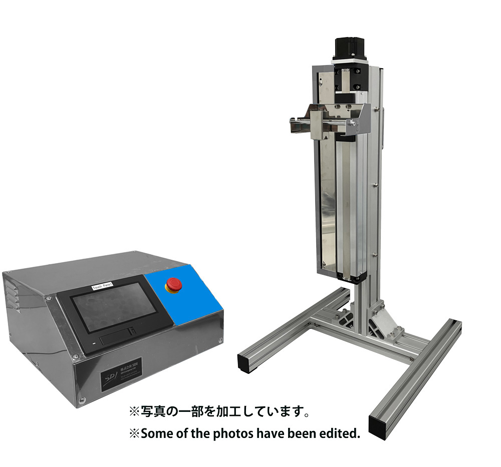







Fabrication of Ceramic Coatings Using the Micro Dip Coater MD-0408-N1
Institute of Biomaterials and Bioengineering, Institute of Science Tokyo
Taishi Yokoi
1. INTRODUCTION
Ceramic coatings are being deployed in a wide range of applications, including medical materials. Representative examples include biocompatible ceramic coatings applied to artificial joints and dental implants. Currently, plasma spraying is the primary process used to apply biocompatible ceramic coatings onto these medical devices. However, coatings produced by plasma spraying are generally thick films, which carry a significant risk of delamination from the substrate. If a coating peels off from the substrate, the implant can no longer remain fixed within the living body, necessitating revision surgery and placing a severe physical burden on the patient. Because thinning the coating is an effective way to prevent delamination, establishing a process to fabricate biocompatible ceramic thin films is expected to contribute substantially to the advancement of medical care. Although several methods exist for thin-film fabrication, this study investigated the synthesis of biocompatible ceramic thin films via dip coating, which enables uniform coating even on complex shapes. For comparison, spin coating was also performed.
2. EXPERIMENTAL METHOD
Biocompatible ceramic powders with a plate-like morphology were synthesized via a wet chemical route. The obtained sample powders were dispersed in an organic solvent to prepare a slurry, which served as the coating solution. Model substrates consisting of silicon wafers (10 mm × 10 mm × 1 mm, used after UV-ozone treatment) were immersed into this coating solution and pulled up at speeds of 0.1, 0.2, 0.5, and 1.0 mm/sec to form films. For spin coating, the same slurry and model substrates were used, with rotation speeds set between 500 and 2000 rpm.
3. RESULTS AND DISCUSSION
Figure 1 displays a representative Atomic Force Microscopy (AFM) image of a sample prepared by dip coating at a withdrawal speed of 0.5 mm/sec. Although the substrate is exposed in a very small area, the vast majority is covered with biocompatible ceramics. When the withdrawal speed was lower than 0.5 mm/sec, the coating coverage decreased (Figure 2). This result is presumed to occur because a lower withdrawal speed results in a thinner slurry film formed on the substrate, leading to an insufficient amount of powder in the slurry to cover the substrate surface.
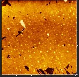
Figure 1. AFM image of the coating fabricated under the condition of 0.5 mm/sec.
On the other hand, at a withdrawal speed of 1.0 mm/sec, low coverage with exposed substrate was observed near the upper portion of the substrate, whereas a heterogeneous structure with stacked particles was observed near the lower portion (Figure 3). This is thought to occur because the withdrawal speed was faster than the evaporation rate of the organic solvent, causing slurry to accumulate near the bottom of the substrate during the final stage of withdrawal (i.e., the portion pulled out from the slurry last), forming a stacked particle structure as the solvent evaporated. Consequently, a withdrawal speed of 0.5 mm/sec was determined to be optimal for the slurry system used in our study.
In contrast, spin coating failed to form a homogeneous structure such as that shown in Figure 1. Regardless of the rotation speed, particle-stacked structures formed at both the center and periphery of the substrate. This difficulty is attributed to the low viscosity and low boiling point of the organic solvent used in this experiment, which resulted in an excessively high evaporation rate.
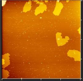
Figure 2. AFM image of the coating fabricated under the condition of 0.1 mm/sec.
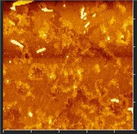
Figure 3. AFM image of the coating fabricated under the condition of 1.0 mm/sec (lower portion of the substrate, pulled out last from the slurry).
4. SUMMARY AND IMPRESSION OF MICRO DIP COATER MD-0408-N1
In this study, the fabrication of biocompatible ceramic coatings was attempted using dip coating and spin coating. As a result, homogeneous coatings were obtained exclusively via dip coating.
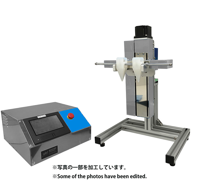
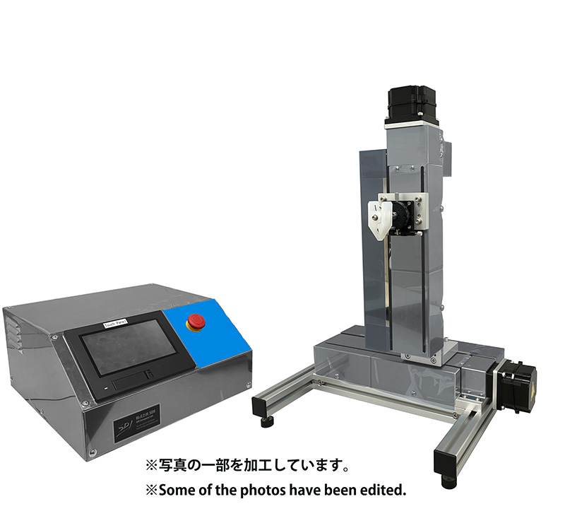
The Micro Dip Coater MD-0408-N1 provides a wide range of withdrawal speed adjustment from low to high speeds, allowing experimental conditions to be varied significantly. Thus, it can be said to be an instrument with sufficient performance even for finding optimal coating conditions in material systems being attempted for the first time, as in our case. Furthermore, the operation of the device itself is simple, enabling even students to start using it immediately after reading the instruction manual (with parallel English text). This was extremely helpful for us, as we conduct research with students at the university. We intend to actively utilize the Micro Dip Coater MD-0408-N1 in our future research endeavors as well.